Cours Arduino
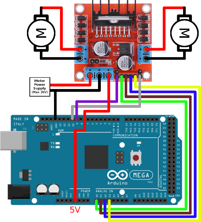
For interfacing, we will employ the RS485 protocol.Similar to our previous tutorial on the Pyranometer Sensor, the RS485 Module will facilitate the transfer of data from the sensor to the Arduino board.The wind speed and direction data will then be displayed on a 16×2 LCD screen connected to the Arduino.. Bill of Materials. Following are the components that we need for Ultrasonic Anemometer.

What Is Arduino
A conversion factor (simply a specific numerical value) is used to convert the duration to kph. You can theoretically determine the CF using wheel diameter, but that will only give you a rough starting point.

RF Based Wireless Message Broadcasting system in Arduino MyCircuits9
If you place the two sensors 1 meter apart, you only need 1ms accuracy to get km/h (assuming a 50km/h speed limit). The Arduino can handle 1ms resolution with ease. I'd probably go with 3-5 meters, so you don't need your setup to be that precise (i.e. distance and alignment of the two sensors). Lowering the distance also makes it less likely.

Arduino RCLF meter Open Source Hardware, Electronics Storage, Shop Layout, Arduino Projects
This is due to the RESET pin being connected to the LCD, which interferes with the Arduino IDE. I read that one could simply connect the RESET pin of the LCD to +5V on the Arduino (permanently), or simply temporarily disconnect the RESET wire while uploading the sketch to the Arduino board. I simply disconnected the power supply when required.
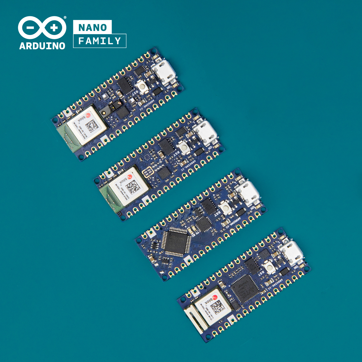
Arduino Introduces 4x new Nano boards ElectronicsLab
At 36 km/h the switch travels 5 mm in 1 ms when mounted halfway the wheel's diameter. So it's fast enough to be activated when it passes the magnet. This document about the same switch gives a life expectancy of > 10\$^7\$ operations, and that's not as much as it seems. If you would do 25 km a day you reach that 10\$^7\$ switch events in 2 years.
AliExpress — Raspberry Pi, Arduino, and Engineering Tutorials — Maker Portal
// calculate the revolutions per milli (second) rpmilli = revolutions/ (millis ()-timeold); timeold = millis (); revolutions = 0; // WHEELCIRC = 2 * PI * radius (in meters) // speed = rpmilli * WHEELCIRC * "milliseconds per hour" / "meters per kilometer" // simplify the equation to reduce the number of floating point operations // speed = rpmi.
avr11 performance measurements Dave Cheney
Start by by placing one resistor at pin 2 on your Arduino. Connect the other end of the resistor to the breadboard and then connect the long leg of the LED to the resistor. Place the short leg of the LED in the outer ground rail of the bread board. Then add 9 more resistors and LEDs across - you should stop at Pin 11 on the Arduino.

About Usarduino
The module communicates with the Arduino via serial communication using the TX and RX pins, so the wiring couldn't be simpler: Getting GPS Raw Data To get raw GPS data you just need to start a serial communication with the GPS module using Software Serial. Continue reading to see how to do that. Parts Required
Alexander Graham Bell Settle facultativ arduino dc motor control sesiune mușca simultan
1 Reed Switch from a bicycle speedometer Project description Even though it sorely needs an improvement, this is a quick and entertaining project, that allows customizations.
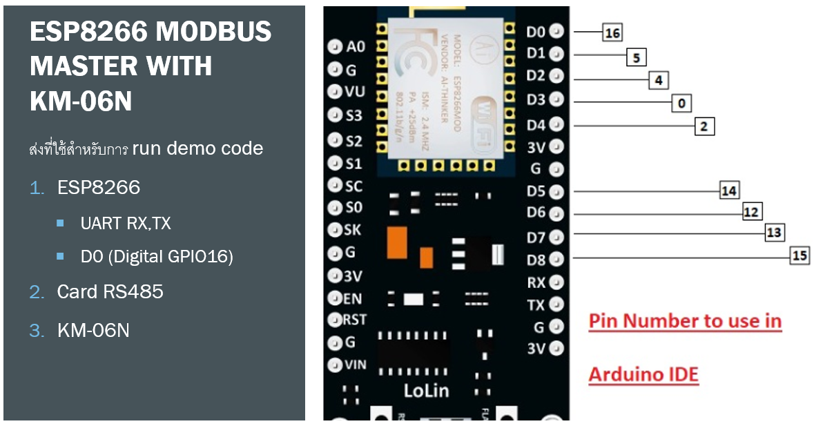
การใช้ Arduino ติดต่อ Meter KM06N ทำอย่างไร? (KM06N 3 Phase Power and Energy Meter With RS485)
Pinout The NEO-6M GPS module includes 4 pins: VCC pin: needs to be connected to VCC (5V) GND pin: needs to be connected to GND (0V) TX pin: is used for serial communication, needs to be connect to Serial (or SoftwareSerial) RX pin on Arduino.
Arduinoesim
The LM393 Speed Sensor is typically connected to an external microcontroller, such as an Arduino board, to measure the pulse signals and perform the necessary calculations. The sensor operates at a supply voltage of 5V and has a low-level output signal of 0V. The frequency of the output signals is proportional to the speed of the rotating.

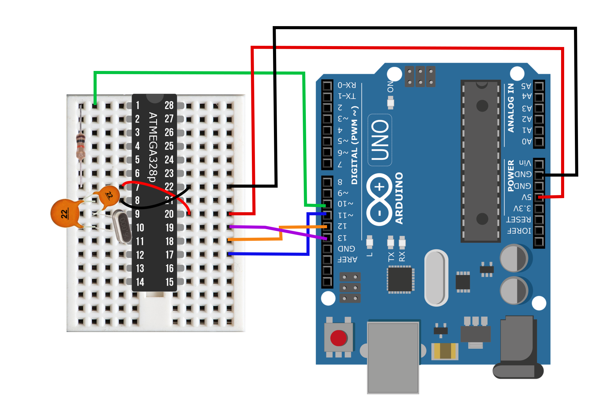
circuit diagram of arduino uno Diagram Board
For my own safety. I got the need for speed and want to reach about 250 km/h on my bike. You need to check if you had hit the goal for the ride, and it takes many meters to lower the eyes and look at the original speedometer.. /*Arduino code for measuring speed and engine rpm using two Hall sensors * * Coding of anITiot.se summer 2018 * 8x7.
Arduino Guide
Using Arduino Project Guidance enzom32 May 12, 2021, 4:10pm 1 Hello guys, in a previous post I learned how to convert the 12v square signal into a 5v square signal for the Arduino input range. The sensor that outputs this type of signal is a hall effect sensor for speed in my car.

Arduino Wikipedia
In this tutorial, we will use a very basic example from the Arduino_MKRGPS library, which records different geolocation data directly from the GPS shield, and prints them in the Serial Monitor. Goals.. - records speed in km/h. The sketch can be found in the snippet below. Upload the sketch to the board. Copy. 1 # include
Arduino Electrathon Telemetry
M 4.6 - 57 km ENE of Los Andes, Chile. 2024-01-11 22:34:24 (UTC) 32.627°S 70.033°W. 112.0 km depth. Interactive Map. Contributed by US 1. Regional Information. Contributed by US 1. Felt Report - Tell Us!

How To Program With Arduino smashmanager
An IR sensor module, which is used to detect fan's blade to calculate the rpm, is connected to interrupt 0 means D2 pin of Arduino. Here we have used a stepper motor driver namely L293N module. IN1, IN2, IN3 and IN4 pin of stepper motor driver is directly connected to D8, D9, D10, and D11 of Arduino. Rest of connections are given in Circuit.
