Connector Wiring
RJ45 Pinouts: Explaining 568A, 568B, Ethernet pin connectors, and crossover cables Ethernet cable Color-coded wiring sequences exist as a cabling industry standard.
Single Pair RJ45 and clarifying the mating interfaces
The industry calls this type of connector 8P8C, shorthand for eight position, eight contact. Ethernet cables and 8P8C connectors must be crimped into the RJ45 wiring pattern to function properly. Technically, 8P8C can be used with other types of connections besides Ethernet; it is also used with RS-232 serial cables, for example.

RJ45 Pinout
RJ45 connectors are most commonly used to connect one internet-enabled device with another network device. For example, a PC connected to a server, router, modem, smart TV, gaming console, or any device utilizing Ethernet protocol.

Cable Wiring Order
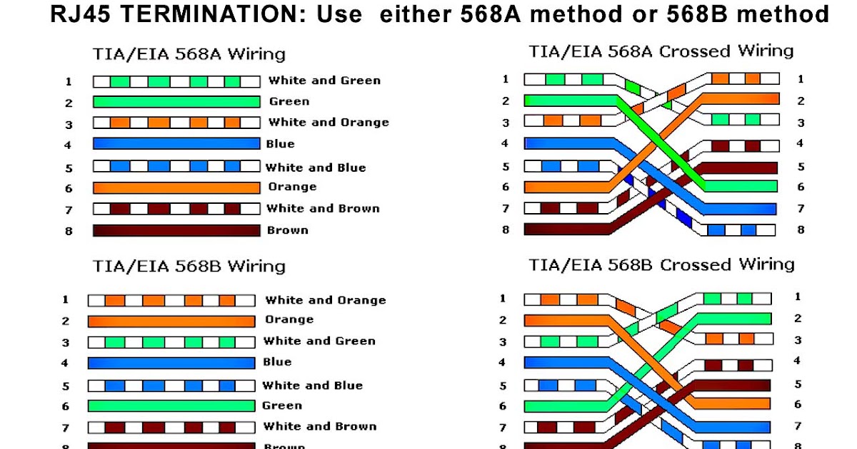
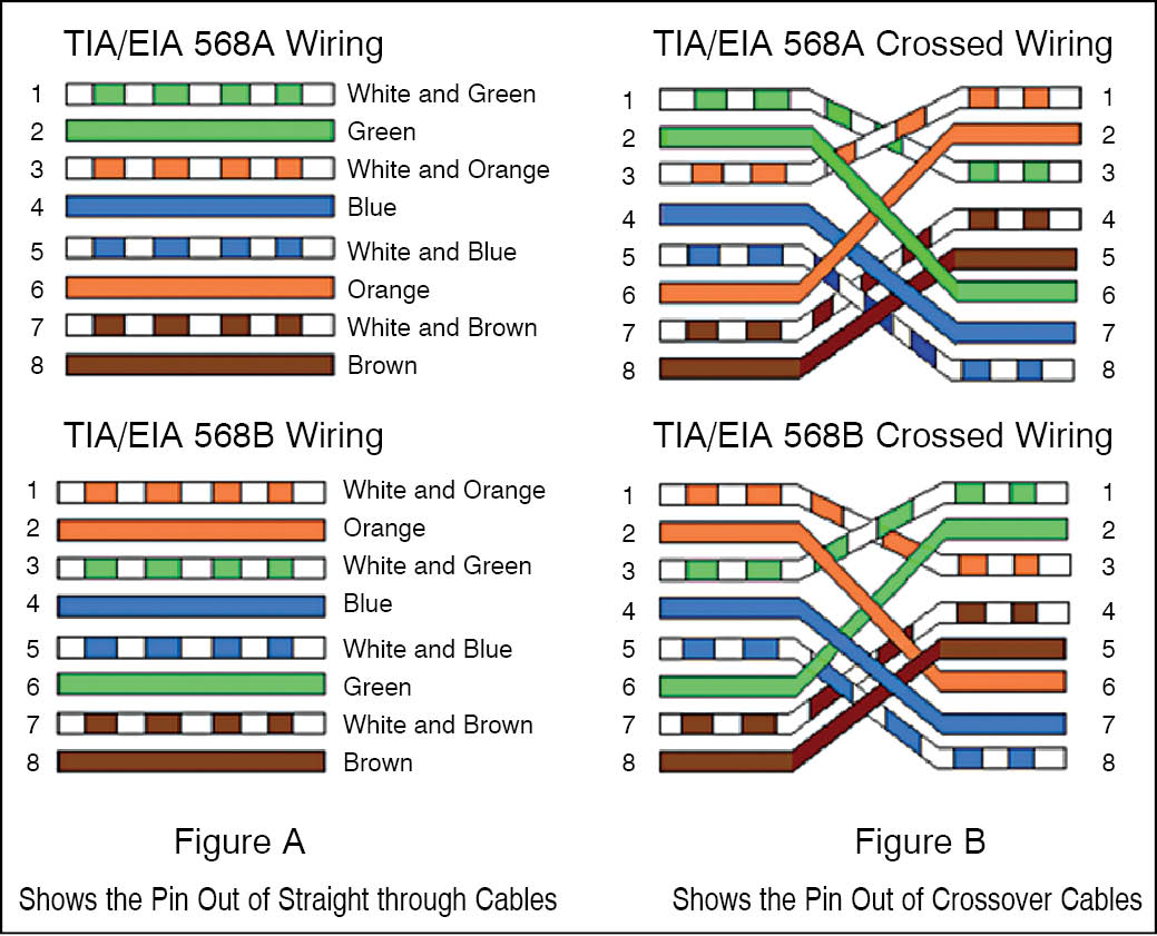
RJ45 R egistered J ack standard number 45 specifies the amount of wires in the cable, the order in which they appear, and the usage of the 8P8C physical connector. Specifically, RJ45 defines two wiring standards: T568a and T568b: Notice the only real difference between the two standards are the colors of wire pair 2 and pair 3.
Wiring Code RJ45 color code Color coding, Electrical
The Ethernet wiring on the camera side differs from that of a typical RJ-45 Ethernet cable's wiring. Below is a representation of how to apply these concepts to a typical RJ-45 connection. Below is a description of the basic functionality of each wire associated with the Ethernet port pins on your camera:

Rj45 Wiring Scheme
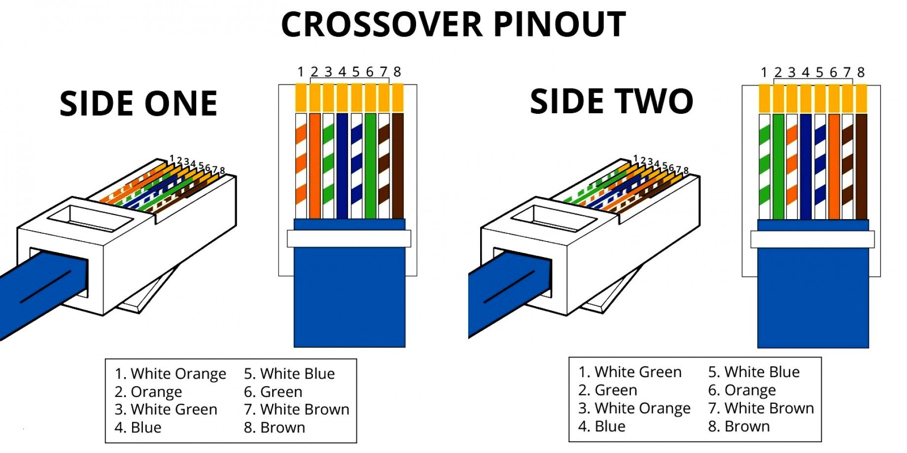
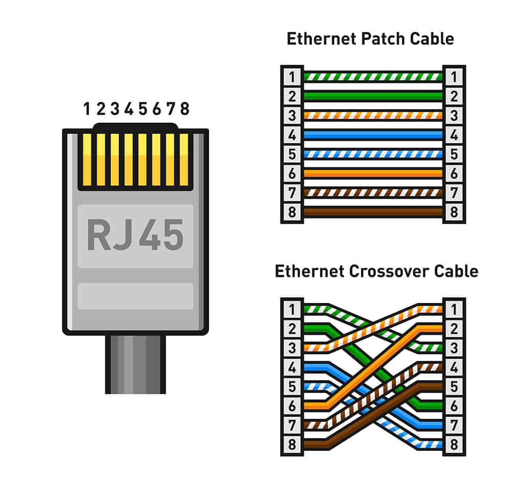
Pinout & Types (Patch, Crossover & more) CAT cables, commonly known as RJ45 cables are used in LAN (Local Area Network) for internet or data transfer. They are available in various categories, like CAT5, CAT6, etc. And also have different types, like Straight cable (Patch cable), and Crossover cable. In this article, we will discuss RJ45 cable.
Rj45 Wiring Diagram T568b
Get up to date on the wiring of an Ethernet cable with our RJ45 connector pinout diagram at Warehouse Cables! We're here to help you understand your wires.
Easy RJ45 Wiring (with RJ45 pinout diagram, steps and video
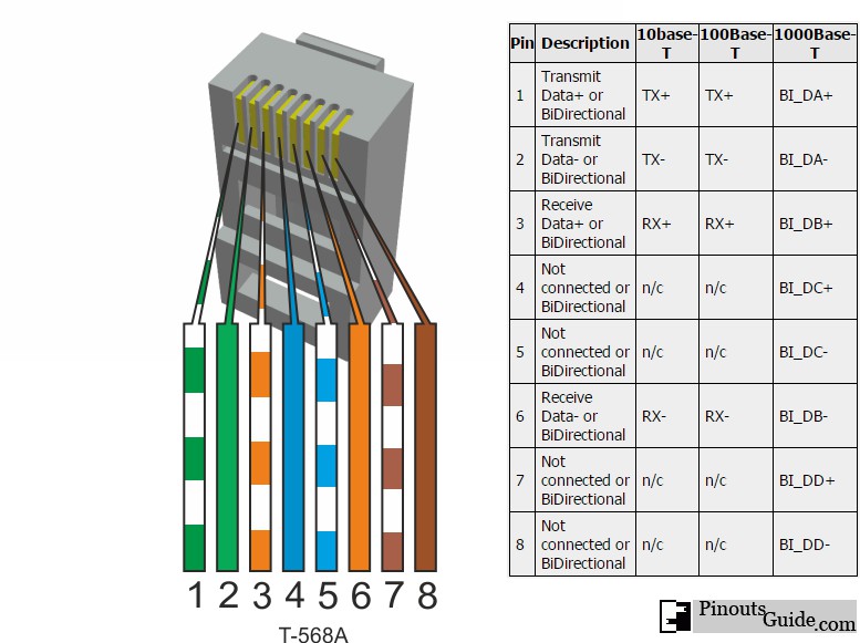
RJ-45 Ethernet Cable Pinout Twisted Pair Cables use RJ-45 (Registered Jack) connector Coming to the main point of this article, the Ethernet Pinout, the TIA/EIA color-coded the four twisted pairs cables as per the TIA/EIA - T568-A or TIA/EIA - T568-B standard. The following table shows the cable colors in each standard.
10/100BaseT ( RJ45) connector pinout diagram pinouts.ru
The RJ45 connector is a modular 8 position, 8 pin connector used for terminating Cat5e or Cat6 twisted pair cable. See the RJ45 Pinout on this page!
Rj45 Wiring Diagram Pc To Pc
The RJ45 connector is a standardized networking connector that is commonly used for Ethernet connections. It is a small, rectangular connector that allows a network cable to be securely plugged into a networking device such as a computer, router, or switch.

rj45 cable color code Wiring Diagram and Schematics
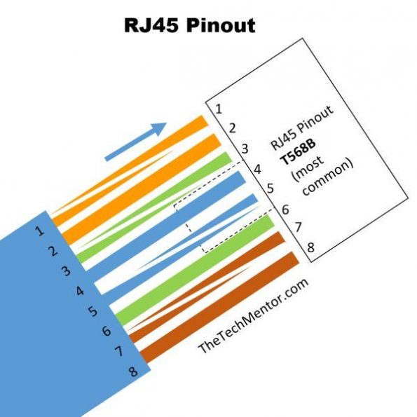
This RJ 45 pin diagram (T-568B) shows everything you need in one handy image, with iso-view and RJ45 color order, suitable for printing quite large. I like this pinout diagram because it shows everything you need. It includes an isometric view and pin-color order table, all in one large diagram.
Color codes for rj45 An ultimate guide on RJ45 wiring colors
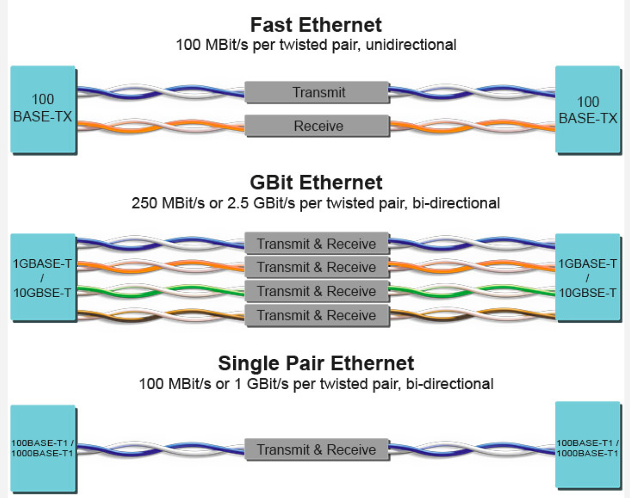
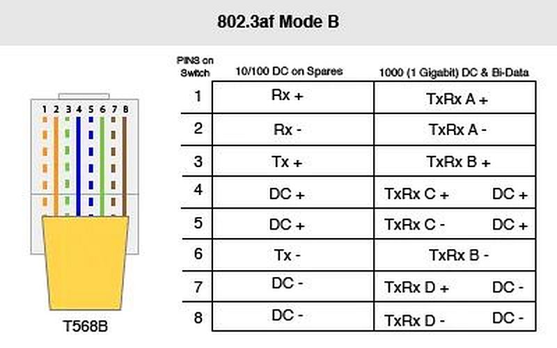
Comment Edit Submit New 1000 Base-T uses all pairs for bidirectional traffic in the RJ45 connector. cables used should be of Category 5e (nhanced), even though Category 5 cables usually works too. 1000BASE-T (also known as IEEE 802.3ab) is a standard for Gigabit Ethernet over copper wiring (RJ45 connection).

Wiring Diagram For
The ethernet cable used to wire a RJ45 connector of network interface card to a hub, switch or network outlet. The cable is called wipe, patch cord, straight-thru cable.
Pinout UTP RJ45 LAN en PoE
Ethernet 10 / 100 Mbit (RJ45 cat 5) network cable wiring pinout Pinouts > Computer Network cables wiring 8 pin RJ45 (8P8C) male connector at the network interface card Ask a question Comment Edit Submit New This is most common cable for 10/100Base-T ethernet networks.

Rj45 Connector Wiring Diagram
RJ45 (Registered Jack 45) is the connector that consists of 8 metal connection point. RJ45 pinout diagram shows the way how that connector provides communication with network devices. RJ45 exists at the end of the ethernet cables that is used for internetwork communication.

Rj45 Cat 5e Wiring Diagram
The rj45 connector has a total of 8 pins and eight colored wires. Moreover, you'll find the colored stripes in 4 twisted pairs. Additionally, the wire pairs are responsible for handling power and signals in a proper electrical connection. The table above describes the TB68B wiring scheme.
