
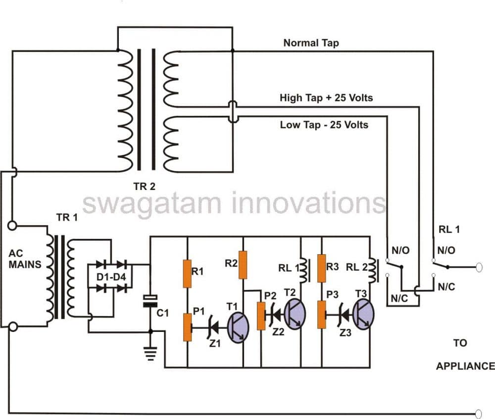
Relay type Automatic voltage stabilizer circuit diagram, 3 relay stabilizer circuit in 2021
The present circuit of triac controlled AC voltage stabilizer is outstanding in its performance and is almost an ideal voltage stabilizer in every respect. As usual the circuit has been exclusively designed by me. It is able to control and dimension the input AC mains voltage accurately through 4 independent steps.

Circuit Diagram For Automatic Voltage Stabilizer
circuit diagram 1. Here is another simple circuit of Autocut For manual stabilizer. In this circuit, there are small changes from the first circuit. if you use a 12-0-12 transformer then use a 24v relay. You can also check this circuit by connecting with a 0-12 transformer with a 12v relay. Use 500ma to 1 A Transformer.

5KVA Voltage Stabilizer Circuit
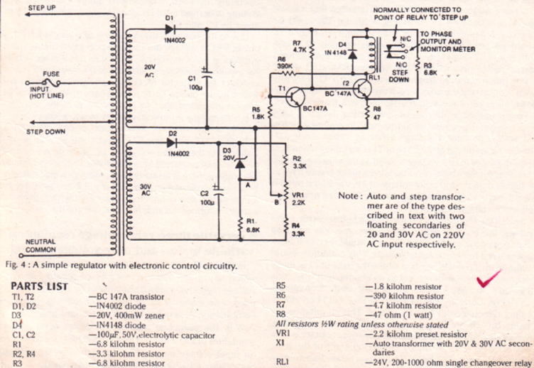
Circuit Description of Automatic Voltage Stabilizer. The power supply to the circuit is given from the secondary coil of transformer X 2. As the voltage between two tappings is 20V, it is directly rectified using a bridge rectifier using diode D 1 through D 4. The rectified output is further filtered using electrolytic capacitor C 1.
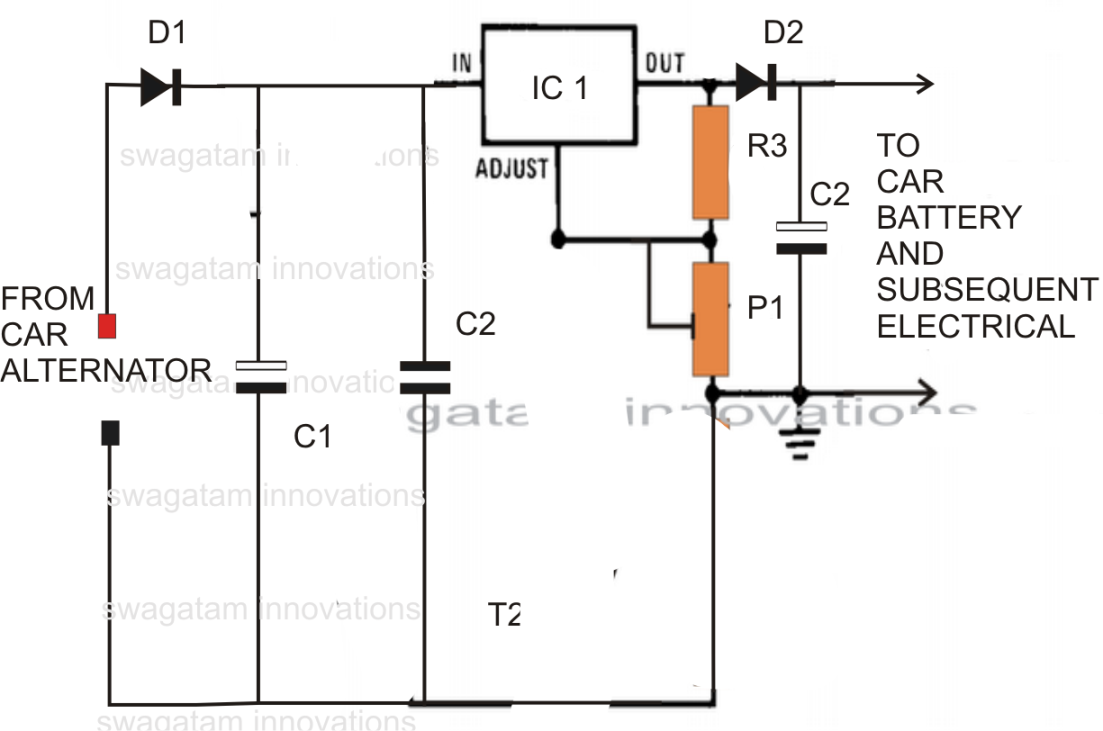
Car Voltage Stabilizer Circuit
Design & Implementation of Emergency Backup Light. May 2014. PDF | On Nov 1, 2014, Utsho A Arefín and others published Design & Construction of a 220V Voltage Stabilizer | Find, read and cite all.
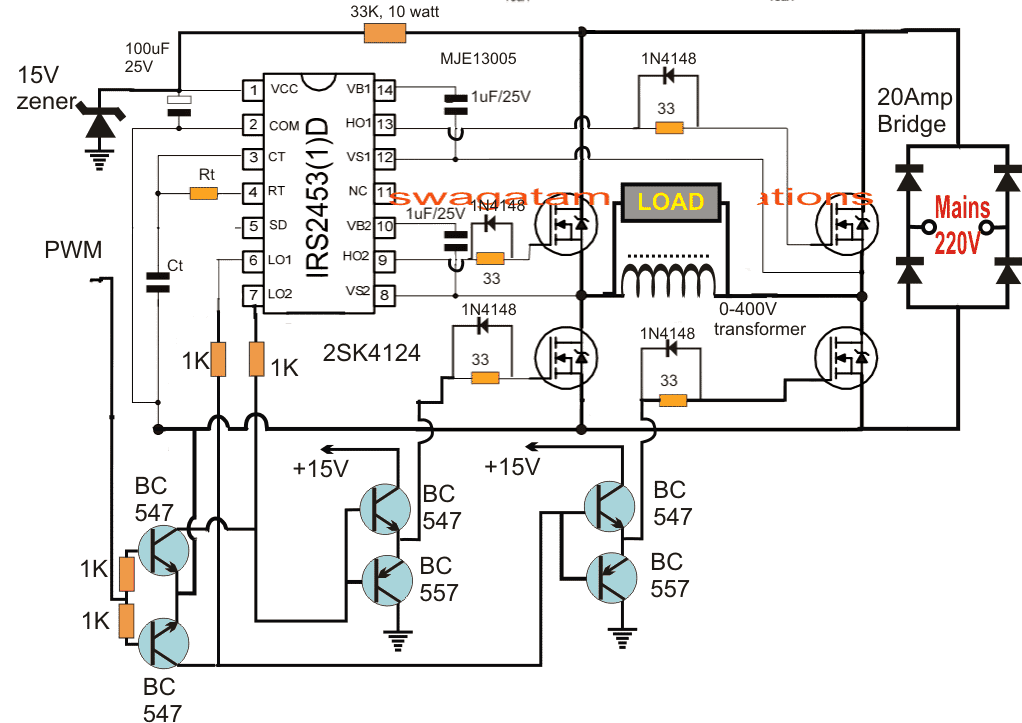
PWM Controlled Voltage Stabilizer Circuit Homemade Circuit Projects
The circuit is very simple and using ULN2003A rather than a set of devices as relay driver with transistor, diode, resistors made the circuit cleaner. Each driver section of ULN2003A is configured with darling tone transistors, resistors, and diodes. The ULN2003A driver IC has common and GND pin from those the GND pin is not shown in the diagram.
2Stage Mains AC Voltage Stabilizer Circuit Homemade Circuit Projects
Abstract: The performance of any current stabilizer can be predicted in terms of two parameters defined as the stabilization transconductance, g s, and the output conductance, g o.Together with the equivalent circuits of Figs. 2 and 3 these two factors permit the calculation of the stabilizer performance in conjunction with any load circuit and direct-current supply.

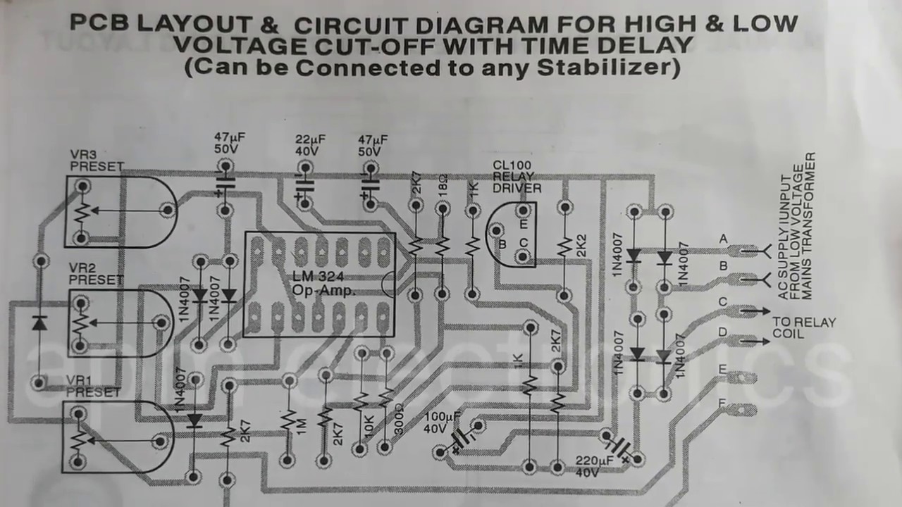
How to design a voltage stabilizer using Relays and LM324 OpAmp and NE555 Timer IC Lab
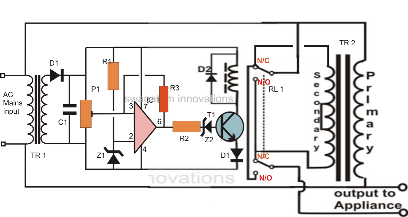
Your simple home made mains voltage stabilizer circuit is ready. When set up, the relay trips at any time the input voltage exceeds 230 volts, bringing the output to 218 volts and keeps this distance constantly as the voltage extends to higher levels. When the voltage falls back to 225, the relay gets de-energized pulling the voltage to 238.

5 KVA to 10 KVA Automatic Voltage Stabilizer Circuit Explained 220 Volts, 120 Volts
Analysis of Voltage Stabilizer Circuit Diagram. The voltage stabilizing circuit of the power supply is composed of power transformer T3, rectifier diodes VDl-VD4, filter capacitor Cl-C3 and three-terminal voltage stabilizing integrated circuits ICl and IC2. The input comparison circuit is made up of resistor Rl, potentiometer RPl-RP9, capacitor.
Simple Mains Voltage Stabilizer Circuit
A servo stabilizer is a servo motor-controlled stabilization system that delivers optimum voltage supply using a buck/boost transformer booster that captures voltage fluctuations from input and regulates current to the correct output. An AC synchronous motor adjusts voltage in clockwise or anticlockwise direction and manages the output voltage.

Automatic Voltage Stabilizer Circuit Best Engineering Projects
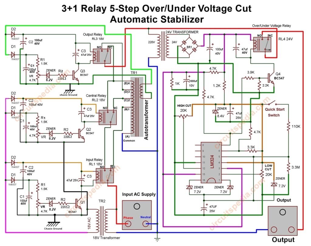
3 relay stabilizer circuit diagram. These are the following schematics diagrams of most using stabilizers. you can troubleshoot or construct a stabilizer by using the following circuit diagrams. this circuit diagram includes 2-relay, 3-relay with IC and without IC and with high voltage auto cut. All are diagrams of the automatic stabilizer.
Stabilizer Circuit DiagramElectronFMUSER FM/TV Broadcast OneStop Supplier
Internal diagram of stabilizer. There are different types of voltage stabilizers available in today's market from various manufacturers. Stabilizers come with a different KVA rating for normal range (to produce 200-240V output with 20-35V boost-buck for input range of 180-270V) as well as a wide range (to produce 190-240V output with 50-55V boost-buck for input range of 140-300V) applications.
Stabilizer Relay Drive Control Circuit diagram IC LM324 YouTube
Figure 1 gives the basic circuit of simple Simple DC voltage stabilizer using zener diode. The zener diode has been connected directly across the load impedance Z L.Hence the output voltage V 0 across the load impedance Z L equals V z, the zener breakdown voltage and is maintained almost constant impite of variations in either the input voltage V i or the load impedance Z L.

Circuit Diagram of the 5 kVA Microcontroller Based Automatic Voltage... Download Scientific
As the circuit diagram you see above, I change a bit for stability & add other components in same board for less space. Connect & Soldier parts according to the schematics. Connection :-Input transformer 12v line to the circuit -> 12VAC in mark area. input Sensor connections. Connect Voltage sensor positive to A0 pin of arduino and Negative to.
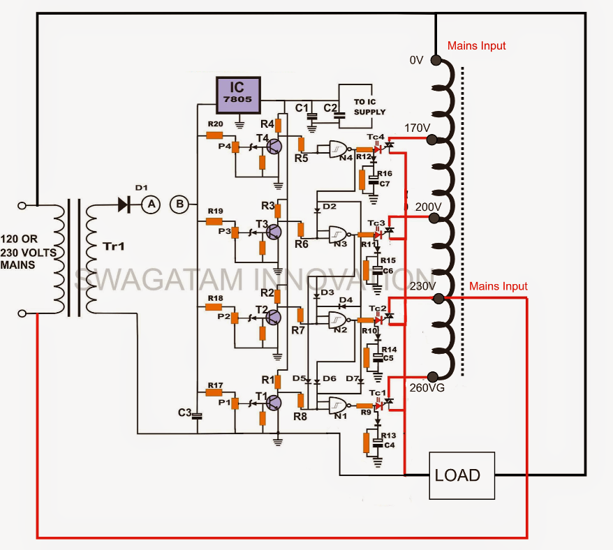
Triac Controlled Mains Voltage Stabilizer Circuit
03 September 2020 11694. A voltage stabilizer is a device that stabilizes the output voltage. The voltage stabilizer is composed of a voltage stabilizer circuit, a control circuit, and a servo motor. When the input voltage or load changes, the control circuit samples, compares, and amplifies, and then drives the servo motor to rotate to change.

Relay Type Automatic Voltage Stabilizer Circuit Diagram
We can build a high power stabilizer by little alteration in the circuit together with a step-up transformer which can be used for refrigerators, TV, washing machines, etc. This low-cost voltage stabilizer circuit diagram reflects that the regulator is controlled by a simple comparator IC LM324. It makes the circuit more effective for.
5 Relay Stabilizer Circuit Diagram
You can assume the maximum 12 volts of the power supply to be equivalent to an input of approximately 230 VAC. We will take this voltage as the trip or the change-over voltage of the stabilizer. Connect the power supply to the supply terminals of the completed circuit board. Keep the voltage of the power supply to its maximum position of 12 volts.
